Step by Step Instructions for Installing the T-550 Frost-free Sillcock
The T-550 is certified to ASSE 1019 Type A. In accordance with Sections 1.2.3 and 1.2.4 of this standard, the T-550's operating pressure shall not exceed 125 psi and the operating temperature range is 33 degrees F to 140 degrees F.
DIAGRAM.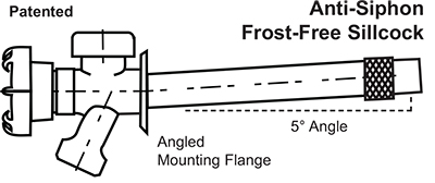
IMPORTANT!
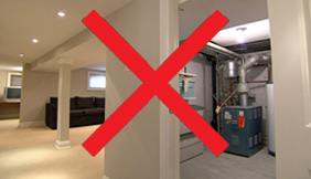
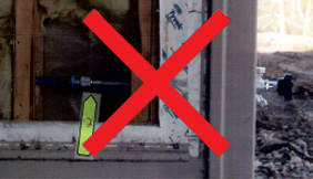
"Frost-free" sillcocks will resist freezing only when the inlet connection is located and exposed within a heated space! Seasonally-heated or non-heated installations (e.g. vacation homes, commercial buildings, garage, crawlspace or wing-wall cavity) require an accessible stop-and-waste valve, to allow winterization, as specified in the IRC Code section P2903.10.
Crawl Space
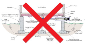
Finished Basement Ceiling
Wing-Wall Cavity
Installation
Step 1: Select Length Needed
Select the correct-length T-550 Confirm that at least two inches of the inlet connection is exposed in the heated space, regardless of sill width. Note the placement of the label attached to the inlet connection, which illustrates how much of the T-550's inlet must extend into the heated space.
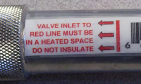
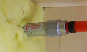
For tool accessibility, the knurled segment should extend well beyond the inner wall face. DO NOT insulate over the inlet connection!
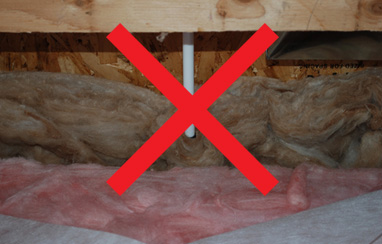
Doing so will insulate it from the surrounding heat. Confirm that the T-550's inlet connection type is compatible with the building's pipe or tubing water supply system.
**NOTE: Installation of the 4" nominal-length T-550 is not recommended in geographic regions subject to freezing temperatures.
STEP 2: Bore Hole
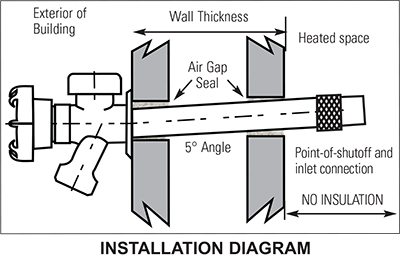
Bore a 1” diameter hole through the foundation wall or the floor joist band pitched upward at a 5° angle. Protect the inlet of the T-550 from debris entry, by placing a piece of tape over the inlet port. Insert the T-550 from the outside.
STEP 3: Position the T-550
Position the T-550 so the outside hose bibb spout is pointed down. Note that the inlet connection is marked with the words "TOP" and "DOWN" indicating spout position. From the inlet side, make sure the "DOWN" mark faces downward, toward the floor or ground.
Step 4: Seal All Air Gaps
IMPORTANT! Seal all air gaps between the back of the mounting flange, the exterior wall and drilled hole. The T-550's mounting flange must fit flush against the exterior wall. If necessary, place the plastic sill wedge behind the mounting flange, notch-side-down, with the words "REMOVE HOSE IN FREEZING WEATHER" facing upward, before securing the mounting flange to the wall. The mounting flange and sill wedge are angled, to assure complete drainage. A flush fit is critical to correct frost-resistant performance; poor drainage could result in trapped water and subsequent freezing damage.
Step 5: Secure Mounting Flange
Secure the mounting flange to the exterior wall with two #8 or #10 exterior grade wood screws of appropriate length. Use the correct type of masonry hardware when attaching to brick or cement.
Step 6: Connect the Inlet
Connect the T-550's inlet to the water supply system. The T-550 is available with:
- 1/2" LegendPress
- 1/2" MNPT x Sweat
- 3/4" MNPT x Sweat
- 1/2" MNPT x FNPT
- 3/4" MNPT x FNPT
- 1/2" Crimp/Cinch PEX
- 1/2" Cold Expansion PEX
- 1/2" CPVC
- Remove the previously-applied tape from the T-550's inlet connection.
- When soldering, make sure the T-550 is in the full-open position by turning the handwheel counter-clockwise. Direct the flame away from the knurled area of the inlet connection. DO NOT OVERHEAT!
- For pipe threaded connections, use Teflon* tape or thread paste. For stability, attach the wrench to the knurled portion of the inlet connection before tightening the fitting or nipple.
- For PEX connections, follow the crimping tool manufacturer's requirements. The T-550's PEX connection is manufactured in compliance with ASTM F1807 and is designed for PEX tubing that complies with ASTM F876 and F877.
- CPVC solvent-weld connections should be made in accordance with the recommended procedures in the PPFA Installation Handbook for CPVC Hot and Cold water piping, or the solvent cement manufacturer's requirements.
CAUTION! Failure to allow proper drainage due to improper installation pitch or a hose left attached to the hose bibb outlet in freezing temperatures, may result in damage.
The T-550's frost-free feature works by shutting off the water in the heated interior of the building and draining the water downstream of the shutoff, where no heat is present. If the building is, or will be unheated for any period of time, all water lines must the be drained, as no heat would be present at the inlet connection of the T-550.
Maintenance
- Always remove hose in freezing temperatures to ensure complete drainage.
- The T-550’s freeze-resistant design permits water shutoff inside of a heated building. However, as specified in the Residential Plumbing Code Section P2903.10, an additional waste-equipped valve may be required: IRC P2903.10 Hose Bibb. Hose bibbs subject to freezing, including "frost-proof" type, shall be equipped with an accessible stop-and-waste-type valve inside the building so that they may be controlled and/or drained during cold periods. Legend recommends the addition of a stop-and-waste-type valve (stop-type or ball-type) upstream of the T-550 in seasonally-heated or non-heated installations such as vacation homes, commercial buildings, garage, crawlspace or wing-wall cavities. The valve should be installed in an accessible location, where the drained water won't damage the surrounding area.
- Avoid painting over the handle, body or vacuum breaker assembly.
- Do not remove the top-mounted vacuum breaker cap. The cap diverts water downward as the vacuum breaker's internal piston operates. It is a normal function of the vacuum breaker to allow some water to escape before the piston closes completely! However, a continuous stream of water flowing from the bottom of the cap indicates a fouled or failed vacuum breaker assembly.
- Intermittent leakage from behind the handwheel is normal under certain operating conditions. When a hose nozzle is attached to the end of a garden hose which is attached to the T-550's outlet, excess backpressure may result. This backpressure is relieved through a small vent hole immediately behind the handwheel. A continuous stream of water flowing from behind the handwheel indicates a failed stem packing or vent.
- Avoid imparting body stresses by not hanging a coiled hose or not stepping onto the installed T-550.
- Avoid the use of hose bibb accessories such as hose manifolds, hose Y-splitters or sprinkler timers, which may cause the T-550 to malfunction. The T-550 is designed and certified in accordance with ASSE Standard 1019 Section 1.2.1, for non-continuous pressure service: Not more than twelve hours of continuous water pressure. Outlet-mounted devices may cause sudden or continuous, damaging back-pressures.
- While the T-550’s body and handle are resistant to most household chemicals, avoid exposure to harsh chemicals, such as acids, paint thinners or bleach. Cover or wrap the T-550 when using a pressure washer, chemical siding wash or brick cleaning formulas.
- Do not force the handle open or closed. The handle will operate in a smooth, quarter-turn operation. If not, check for obstructions (debris, rocks, etc.) behind the handle. If after checking, the handle still does not operate in a smooth, continuous manner, contact a licensed contractor. • Annually, check the screws that attach the sill flange to the sill. Make sure they hold the T-550 firmly, without allowing movement.
- Do not attempt to disassemble or service the T-550. A qualified, licensed contractor should be contacted in the event of a malfunction or failure.